Hi if you are looking for a plasma globe driver or you want to make an ignition coil that zaps things, you have come to the right place. Recommended for people experienced in electronics only!
If your interested in jets here is mine: http://www.youtube.com/watch?v=_t8qsfF32TI
http://www.youtube.com/watch?v=G_2OUc3sqHk
First some safety issues; this project runs off 240v AC or 120v AC so please be very careful as house hold current can kill instantly, if you touch a live wire your hand will grab the wire and you wont be able to let go. I found this out the hard way. So do not make the same mistake as me. Oh when sparks jump to the earth they generate ozone which can kill if you breath in to much , only small amounts exist in this case. I am not responsible if any property of yours is damaged or you or some one is injured in the process of making this.
To make this the components you will require are:
An ignition coil the old sort.
A light dimmer preferably over 1.5amps or 400w
Wire any sort
A large light globe incandescent for the plasma globe
A container if your making a plasma globe
A cord that can plug in to the power point, please don't take the one of the TV or fridge find an old one that is no longer needed.
Some oil and a jar if you have a low rated dimmer.
A hot glue gun is very handy in making something like this.
- How To Build A Ignition Control Module
- Model A Ignition Coil
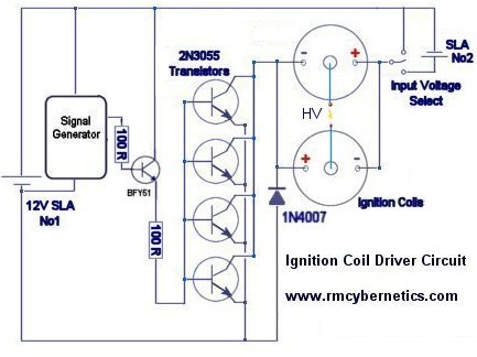
- Ignition Coil Driver Schematic
- How To Make Ignition Coil Driver
The enable pin allows to externally block the switch when the input is on. A built-in protection circuit for coil current limit ing and collector voltage clamping allows the device to be used as a smart, high voltage, high current interface in advanced electronic ignition systems. A faulty ignition coil can also lead to a no-start condition. For vehicles that use a single ignition coil as the source of spark for all of the cylinders, a faulty coil will affect the operation of the entire engine. If the coil fails completely, it will leave the engine without spark, which will result in a no spark, no-start condition. OK, an ignition coi l (or spark coil) is a type of induction coil similar to a Tesla coil. It's used in combustion engines. And produces up to 50,000 volts (a 2-4CM spark) at a lethal current of 25ma.
How To Build A Ignition Control Module
To run the ignition coil outside of the car, specialised circuitry is required that produces pulses of voltage to the primary coil. I took a very common design (a 555 timer driving a MOSFET) and built it. Well, more like lashed it up. As seen in photo. In the photo, it shows the initial setup with two ignition coils. The Shocking Truth: How To Make High-Voltage Sparks. By Vin Marshall posted Dec 18th, 2009 at 12:39pm. In the case of an automotive ignition coil, we're talking about very high voltage. Feb 14, 2014 Check out the step-by-step video to build this circuit: A very simple 555 timer driver circuit powering an old ignition coil with some. Hi if you are looking for a plasma globe driver or you want to make an ignition coil that zaps things, you have come to the right place. Recommended for people experienced in electronics only!
this is my schematic its easy, but it, with my power source, only makes about 20 KV (1 inch arc) at a low fixed freq. it's also noisy but still very cool. this makes VERY small streamers due to its frequency. and makes cool plasma globes out of light bulbs.
Note: be sure to use high current capable relays, automotive relays are a good choice. This circuit will inevitably destroy any relay, due to arcing at the contacts accelerating corrosion and excessive heat eventually melting the relay. The power supply must also be capable of maintaining constant voltage at the frequency of operation. Adding a large (1000uF+) of capacitors is needed to minimize stress to the power supply. Do not power this circuit with lithium ion batteries or an expensive supply.
Theory of operation:
Model A Ignition Coil
Upon the application of a power supply, current briefly flows through the capacitor and coil. This is the start of 'ringing' due to the action of the capacitor and inductance of the coil. When the voltage across the capacitor reaches a high enough value, the relay engages, shorting the capacitor. Doing so causes the relay to disengage and another 'ping' to this resonant tank circuit, continuing the oscillation. The frequency is set by the value of the primary inductance of your chosen coil pack or ignition coil, the impedance of the relay coil, the value of the capacitor, and the time taken for the contacts to close.
As can be seen, this circuit will result in large current pulses through the NO contacts as the energy of the capacitor is dissipated there, and large voltage spikes on the primary on the NC contacts, accelerating corrosion and damage.


Ignition Coil Driver Schematic
Use-case:
How To Make Ignition Coil Driver
Despite causing damage to the relay, this circuit is fun to play with, and is a quick an dirty way to test coil packs and ignition coils. The shocks from the circuit are very painful but generally not too dangerous (when operated at 12V) as the power output is limited. Of course caution should be exercised around such a circuit for obvious reasons.